R (render) key select the render mode (solid or wire frame)
Chimera
Script reference
v2.04 OSX and Windows
*** obsolete, still working, i need
to update a lot of statements **
Chimera is a 3D powerful engine completely driven by
scripts.
The "script" is a text file, containing statements, variables, loading
and disposing operations ... in short it is like an interpreted program
written in a language similar to C++. On startup, the engine opens the
scene (the scene file, selected in Settings), then searches and executes
the "script". The script is the core of your scene, it
handles EVERYTHING from the loading operations of objects, sounds and
textures, to positionments and effects.
The purpose of this reference is a comprehensive script explanation.
Sections
How to
Keyboard Map
Syntax and conventions
Basic language keywords
Load Delete New
Scene
Object
Shadow
LightGlow
LightBloom
Blur
CSG
Texgfx
Radio
Water
Fluide
Particle
Flare and Lensflares
Light
Skybox
Keyframer
Deform
To build a scene put the Chimera application
where you want then, in the same folder, create a folder named Data
By default the engine executes the content of the Data folder.
Put all you will need for your scene - objects, sounds, textures and
music – in this Data folder and launch Chimera.
In the data folder acceptable file formats are:
- script.txt the main
script file;
- objects: 3DS
(3DStudio), OBJ (portable Alias Wavefront) and proprietary GFX;
- textures(*): JPG,PNG all Quicktime valid format and Quicktime
movies (for OS X), AVI movies (for Windows);
- effects: VP (vertex program)
and FP (fragment program);
| mouse button LEFT | rotation scene or objects |
| mouse wheel | position forward / backward |
| C (Camera mode) | cycle
thru different camera mode: spin camera : the camera rotation around the scene, pointing always at the origin; position camera: the standard camera mode, like an FPS game; object 0 to (n): each object is focused for rotation |
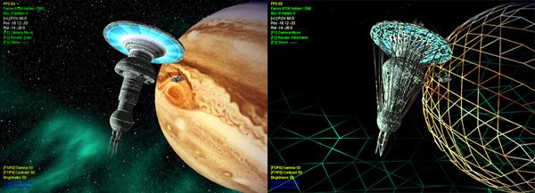
| D (Draw mode) | cycle thru two different render mode: solid and wire frame |
| I (Info) | at
each press it show various information about objects: a) bounding boxes of all the objects; b) show id for any vertex of all objects (useful to control vertex displacement in object or assigning flare or particles to an object) c) show id for any face of all objects; d) vector of the keyframers path (camera keyframer hilited in yellow, object keyframers in green) |
| F
(FPS) |
show the current displayed triangle count ant the current framerate |
| Keyboard 1
and 2 |
STEREO
MODE ONLY increase or decrease eye angle |
| Keyboard 3
and 4 |
STEREO
MODE ONLY increase or decrease eye separation |
R (render) key select the render mode (solid or wire frame)
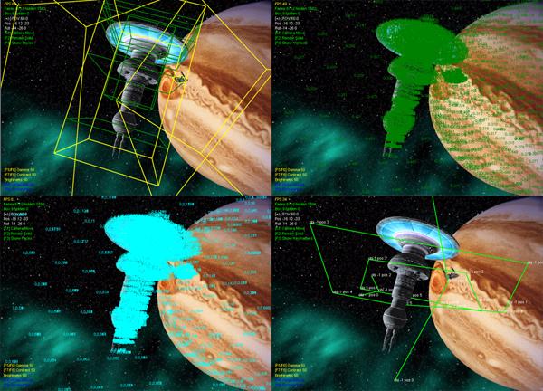
I (info) key cycle from (upper left to lower right): a) bounding boxes,
b) id for any vertex
c) id for any face, d) vectors of keyframer's paths
First of all let’s get a look at basic script
syntax.
If you already have a basic knowledge of the C
programming language you are OK, otherwise ... well, it is not very
difficult to understand anyway, the basic syntax is quite similar to C,
any instruction must be ended by a semicolon (";").
This is the quickest script you can write:
scene start;
Variables are ONLY floating point, but the
engine uses them automatically as integers, short etc,
There's no char or string definitions (c'mon, if you want to write
something cool on the screen you must use a cool texture...).
Variable declaration is unnecessary, as a variable is declared directly
thru assignment, here are some examples:
a =
1;
//declare and assign "a"
b = sin(a); //...and b
The full math syntax/operators of C are valid:
a *= c;
//equivalent to...
a = a*c;
a !=b;
a = (c++); //etc etc...
/* unused line */
It is possible to declare an array
and use it through indexing:
array a[200];
a[27]=sin(b*c);
IMPORTANT! As in C, please keep in mind that
the script language is CASE SENSITIVE:
A = 100;
b = A * 100; //ok
b = a * 100; //WRONG!!!! "a" is not "A"
MYSHIP = load("BUCKROGERS");
delete MYSHIP; //ok
delete myShip; //WRONG!!!!
The data handlers (object, flares etc..) are
organized with identifiers. If you first declare an object as:
myShip = load("ship");
myFlare = new cFlare();
then you can use the myShip
and myFlare
identifiers thru the script:
object myShip position(10,20,10);
flare myFlare color(1,1,0);
For those familiar with OOP: just imagine you're
using a class without the "->" , the previous statement is like:
myShip->position()...
and, of course, you can state:
delete myShip;
delete myFlare;
That isn't strictly necessary though, as the engine
will automatically deallocate all open resources on exit.
Basic keywords(you can NOT use them as variable
names, they are used, for example, in load, delete and other
statements:
| light, object, framer, deform, scene, texgfx, water, fluide, particle, flare, skybox, load, delete, new, status, radio,audiomon,glow,bloom,blur,shadow,csg,all | statements
and operators used by the engine tip: please note that all keywords are lowercase... so use uppercase variables and you'll avoid all problems! FLARE = new cFlare(); flare FLARE position(10,0,0); TIME = time; |
| cLight, cObject, cFramer, cDeform, cScene, cTexgfx, cWater, cFluide, cParticle, cFlare, cSkybox, cStatus, cRadio, cGlow,cBloom,cBlur,cShadow,cSG,all | base classes used by engine |
| sin | x = sin(a); |
| cos | x = cos(a); |
| tan | x = tan(a); |
| asin | x = asin(a); |
| acos | x = acos(a); |
| atan | x = atan(a); |
| sqrt | x = sqrt(a); |
| rnd random |
x = random(minRange,maxRange); |
| time | curTime = time; |
| array | this
is a declaration, eg.:array c[10] the "array" is not "pretty" C, but it is the only declaration you need: int a; //WRONG a = 100; //ok array a[22]; //ok |
| sleep | stop process for n milliseconds, eg.: Sleep(1000) |
| if ... else | :-) |
| while | |
| for |
the if .. else,
while and
for statement have the
same syntax as in C
remember you're using a sort of advanced scripting system :-) so you can
combine functions:
for (c=0;c<100;c++){
... //note: "c" is auto declared
while (a+=0.1 <= sin(z){ ....
a = sin(0.1);
array c[20];
c = atan(a);
if (a*b = 1 && p<c[10]){ .... }else{ .... };
the random,
sleep and
time statement can be
useful:
/* stops the script execution for 2 seconds */
sleep(2000);
/* get a random position from -100 to +100 range
object_position = random(-100,+100);
/* time is useful for sync effects */
currTime = time;
while (time<currTime + 5000)
currTime = time;
Notes for non-programmers
the script engine has full support of functions and
variables ... "compressing" code is vital (but not compulsory) for speed
and readability, for example this code:
object STARSHIP
diffuse(0,0,0);
//this sets STARSHIP object with diffuse color black
object STARSHIP diffuse(0.5,0.5,0.5); //this
sets STARSHIP object with diffuse color gray
object STARSHIP
diffuse(1,1,1);
//this
sets STARSHIP object with diffuse color white
is equivalent to:
COLOR = 0;
object STARSHIP diffuse(COLOR ,COLOR ,COLOR );
COLOR = 0.5;
object STARSHIP diffuse(COLOR ,COLOR ,COLOR );
COLOR = 0.6;
object STARSHIP diffuse(COLOR ,COLOR ,COLOR );
and, in a more appropriate and short form, it is
also equivalent to:
for (COLOR=0;COLOR<=1;COLOR+=0.5)
object STARSHIP diffuse(COLOR ,COLOR ,COLOR );
if you want to assign random colors to the STARSHIP
object, you can specify:
COLOR = random(0,1);
object STARSHIP diffuse(COLOR ,COLOR ,COLOR );
or, better, put the functions directly into the
statement:
object STARSHIP diffuse(random(0,1),random(0,1),random(0,1));
the load function returns an index to an
entity, for example an object, or a particle, or a texture:
SHIP = load("DISCOVERY");
newTexture = load("bigImage");
the load operation always refers to files already in
the DATA folder, remember you can't use extensions:
SHIP =
load("DISCOVERY");
//ok
SHIP = load("DISCOVERY.3DS"); //WRONG
the engine automatically detects the right extension
and loads the object (if the format is supported, of course...).
Loading textures or vertex programs doesn't require allocation, so they
can be reused later in other classes, for example:
lightTexture = load("lamp");
darkTexture = load("lampoff");
....
flare BigLamp texture(lightTexture);
flare BigLamp texture(darkTexture);
....
particle Smoke texture(darkTexture);
are equivalent to:
flare BigLamp texture(load("lamp"));
flare BigLamp texture(load("lampoff"));
....
particle Smoke texture(load("lampoff"));
but the first one is nicer because the texture
allocation is just one
This function varies from class to class, so I put a better
explanation in the chapters regarding the various classes (object,
particle, flare etc.)
For Example
id lampShader = load("lamp"));
Seach for
LAMP.FRAG and LAMP.VERT and combine all into a program, no problem if
one is missing the engine uses only the part found (vertex or fragment).
delete statement disposes of the
specified identifier:
myShip = load("DISCOVERY");
myFlare = new cFlare();
delete cObject(myShip);
delete cFlare(myFlare);
Once again, it is not necessary to dispose of all
entities, as the engine automatically closes all opened resources on
exit.
Use this statement only for your convenience ... for example if you want
to dispose of an object and load another.
Keep in mind that you can use the "active" statement to disable an effect, or to hide an object, without disposing of it:
SHIP = load("DISCOVERY");
object SHIP active(0); //object is now hidden
The new function allocates a new class,
representing an object, effect, etc:
MYFLARE = new cFlare();
Usually classes can be allocated on-the-fly, only
object
class doesnt require "new" but "load", for example:
mySeaPlane = new
cWater();
//right, this is an "effect operator", not a "real object"
myStarship = new
cObject();
//wrong, an object must have a geometry!!
myStarship = load ("StasrhipMine"); //right, an object
is allocated during loading
scene statements control camera(s), the
general appearance of the scene and the user input (if enabled):
| scene start | starts the rendering process, usually called after a scene preparation |
| scene stop | stops the rendering process |
| scene draw(mode) | defines
the current drawing mode 0=wire frame 1=solid please note, some cards are really slow in wire frame mode |
| scene fogrange(near,far) | sets
the current range in which fog is present (from near the observer
to far). Fog is disabled by default : if you specify different values for near and far the fog effect is enabled. |
| scene fogcolor(r,g,b) | sets the current fog color (0,0,0=black, 1,1,1=white) |
| scene fov(angle) | sets
the current field-of-vision, or the angle of vision. The camera uses an angle of 60 degrees by default, so fish-eye views, for example, can be defined as: scene fov(180) |
| scene clip(min,max) | sets the range where objects are visible. Defaults are min=1 max=8000, you can increase max in very large scale scenes |
| scene camera(min,max,angle) | this combines "clip" and "fov" in a single statement |
| scene color(r,g,b) | sets the current background color (0,0,0=black, 1,1,1=white) |
| scene transp(level) | sets
the current level for alpha testing (range from 0.0 to 1.0, if 0
alpha test is disabled) this level affects the object transp(on/off) statement |
| scene fade(r,g,b,a,step) | renders
a fading transition, the final result is the specified color(rgb). The transition is done by incrementing or decrementing transparency (from the value a in "step" steps). For example: scene fade(0,0,0,0,+0.1); means a transition starting with a black, invisible screen (because a=0) and ending with solid black, using +0.1 steps scene fade(0,0,0,1,-0.1); transition start with solid black (0,0,0 and a=1, solid) and end with the same color but full transparent |
| scene size(x,y) | sets the view size (renderable area) to x and y dimensions |
| scene wantfps(framerate) | sets the current framerate |
| scene shadowcol (r,g,b,a) | set the global shadow color (rgb) and transparency (a) (default is 0,0,0,0.4) |
| scene tfilter(value) | sets
the texture filter to be used for any object of the scene. By default the current texture filter is sets by the Settings dialog. valid values and corresponding filters are: 0 = NO FILTER 1 = BILINEAR 2 = BILINEAR MIPMAPPED 3 = BILINEAR ANISOTROPIC 4 = BILINEAR MIPMAPPED ANISOTROPIC 5 = TRILINEAR MIPMAPPED 6 = TRILINEAR MIPMAPPED ANISOTROPIC any other values are interpreted as BILINEAR MIPMAPPED. Note: the ANISOTROPIC mode requires an hardware support, if the appropriate hardware isn't detected the engine automatically switch to a lower value. If you plan to use reflections onto a secondary texture (eg.:lightmaps) do not use any MIPMAPPED mode |
| scene swaptex(tex_id1,tex_id2) | swaps the two textures |
| scene
cleanup |
free all |
CAMERA MOVEMENTS
| scene position(x,y,z) | this sets the camera (observer) position thru x,y,z coordinates (see below) |
| scene rotation(rx,ry,rz) | this sets the camera (observer) rotation thru angles rx,ry,rz (in degrees) |
| scene setspin(angle_x,angle_y) | sets the spin camera at angle_x,angle_y ((the spin camera always looks in the center of the scene) |
| scene spincam(inc_x,inc_y) | spins the camera by inc_x,inc_y angles (the spin camera always looks in the center of the scene) |
you can position a camera with simple statements:
scene position(1,0,0);
scene position(2,0,0);
scene position(3,0,0);
scene position(4,0,0);
or functions:
for (pos_x = 0; pos_x < 100; pos_x ++)
{
scene position(pos_x,0,0);
sleep(100);
}
for (t=0;t<1000;t++)
scene position(random(0,500),random(0,500),random(0,500));
the best way to move a camera in a smooth movement is thru a
"keyframer", a keyframer
makes a smooth trajectory where you define only the waypoints.
Click on the keyframer
link for more samples
USER
INTERACTION
The following statements controls the user input relative to camera
movement.
They are valid only if user input is enabled with scene
keybd(1) (ignored in debug mode)
| scene keybd(0/1) | enables(1)
or disables(0) the user input (ie: mouse AND keyboard) |
|
| scene speed(movement,rotation) | set the current speed and angle speed for the user input (eg.:the mouse speed) | |
| scene focus(OBJECT) | switch the user control from the standard camera (-1) to spin (-2) to object OBJECT | |
| scene collide(0/1) | enables(1) or disable(0) collision detection for the camera vs all objects |
To gain more control about objects selection and status of keypressed buttons during script execution see the status function
CUBEMAPPING
| scene cubemap | this loads and enables cubemapping |
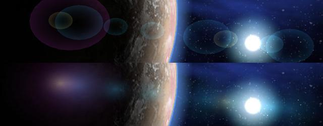
Cubemapping is a very cool environment mapping mode,
available only on newest videocards.
Cubemapping requires SIX textures, representing the environment, and
these six textures are envmapped on the objects.
To enable cubemap you must have SIX textures named cubemap_xxx where
"xxx" is the orientation (left, top, right, bottom, front and back) for
example CUBEMAP_FRONT.TGA
and CUBEMAP_BOTTOM.JPG
are both valid, the orientation follows the "standard" defined by nVidia
in their demos:
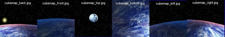
All six textures must be equal in depth (eg.: all of
them 24bit per pixel) and size (eg.:all of them 256x256 pixels) ...
sorry this is imposed by hardware.
The cubemap will be applied automatically on objects with envmapping
textures, if the hardware can't support cubemapping the engine uses
automatically the standard envmapping.
To apply a standard envmapping on a object check the
object
statement.
Tip: since cubemap is better if it's coherent with the visibile
background ;-) you can define a skybox
using the SAME SET of textures, for example:
SKY = new
cSkybox; //create a skybox
skybox ("cubemap"); //load a skybox with the
same standard (cubemap_left etc etc);
skybox active(1);
scene
cubemap;
//activate cubemap, now reflections on the object are coherent with
environment!!
It's possible to enable a separate set of cubemap
for every object, check the texturing
chapter for more info.
It's possible to enable realtime cubemapping over an object, check the
texgfx chapter
for more info.
VERTEX and FRAGMENT PROGRAMS
It is possible to apply a vertex
program (also know as vertex shader
in DirectX programming) or a fragment program (also know as pixel
shader) on every object .These programs are very powerful programs
running straight on the GPU (leaving free your cpu ...and requires
hardware support of course).
The use of GPU programming is only limited by your imagination, because
they can control :colors, texture coordinates, lighting and vertex
position in realtime .
These program must be written and placed in the scene file then we
instruct a main scene to load and apply on objects.
Since vertex and fragment programs can be shared by different objects
they must be loaded like textures and assigned in the general "scene"
class.
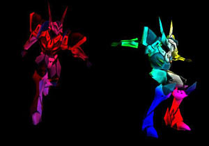
(left: sample vertex colors, right: cel shading)
| scene
vprog(OBJECT_ID,SHADER_ID) scene shader(OBJECT_ID,SHADER_ID) scene glsl(OBJECT_ID,SHADER_ID) |
assign
the previously loaded vertex program SHADER_ID on the object
OBJECT_ID. If "glsl" is used the engine uses vertex (if present) or fragment shader (if present) for the object, see the load section |
| scene
fprog(OBJECT_ID,SHADER_ID) |
assign the previously loaded fragment program SHADER_ID on the object OBJECT_ID |
| scene
vpparm(SHADER_ID,p1,p2,p3,p4) scene shadparm(SHADER_ID,p1,p2,p3,p4) |
pass
the four parameters (p1,p2,p3,p4) to the vertex program identified
by SHADER_ID. Use of these parameters is optional and depends from the vertex program itself. |
| scene fpparm(SHADER_ID,p1,p2,p3,p4) | pass
the four parameters (p1,p2,p3,p4) to the fragment program
identified by SHADER_ID. Use of these parameters is optional and depends from the fragment program itself. |
the following example loads a vertex program and
assigns it to an object:
....
tekkaman = load("blade");
object tekkaman active(1);
....
perturbVP = load("perturbVP");
scene vprog(tekkaman,perturbVP);
if the shader is used once and for just a single
object you can compress code:
scene shader(tekkaman,load("perturbVP"));
for convenience a shader can be called by scene and
object, the following statement are equivalent:
scene vprog(tekkaman,perturbVP);
object tekkaman shader(perturbVP);
if you need to send a parameter to the shader call:
scene
vpparm(perturbVP,0,0,-100,time); //shader "perturbVP"
receive 0,0,-100 and the current time
In the Chimera "SDK" distribution you can
find some samples of vertex programming.
The object class is the core of the engine,
because without objects, it is hard to make a scene :-), acceptable
object format may be 3DS, OBJ, MD2 and others.
It is possible to apply a vertex
program to every object.
When first loaded, the original file will be converted in GFX
format, which is smaller and more suitable for the engine.
The original object file may contain a single object with a single
material or multiple object and material definitions.
Materials are a good source of effects because an effect (envmapping,
bumpmapping and so on...) can be assigned on a specified material.
Material effects are automatically applied if the corresponding texture
is found, for example, material covered by texture "TERRAIN.TGA" will
show bumpmaps AUTOMATICALLY if "TERRAIN_BUMP.TGA" is found (see
texturing)
| ID = load (fileName) | load an object-definition from a file (file definitions are not considered in this reference) |
| delete cObject(ID) | delete an object |
| object ID active (0/1) | enable (1) or disable(0) the ID drawing |
| object ID update | force an update to entire object (usually you don’t use this statement) |
| object ID diffuse (r,g,b) | specify a diffuse color for the object (valid range 0..1); |
| object ID ambient (r,g,b) | specify an ambient color for the object (valid range 0..1) |
| object ID specular (r,g,b) | specify a specular color for the object (valid range 0..1) |
| object ID blend(a) | set a transparency level for the object (valid range 0..1) |
| object ID alpha(a) | change the transparency level of the object (valid range 0..1) |
| object ID lighted(0/1) | illumination is cast(1) or not cast (0) on this object |
| object ID smooth(0/1) | turn on/off the "smoothing" effect of lights on a lighted object |
| object ID transp(0/1) | turn
on/off the alpha test for this object to change the alpha level use the scene transp(level) statement |
| object ID fog(0/1) | turn on/off the fog effect for this object |
| object ID drawmode(0/1) | switch between solid rendering and wireframe |
| object ID lmmode(0/1) | switch between lightmapping and shadowmapping (only if object uses lightmaps) |
| object ID envmode(0/1) | set current envmaps drawing mode (only if object uses envmaps) |
| object ID bumplevel(1) | set current bumpmaps height (only if object uses bumpmaps), default height is 0.008 |
| object ID deftex(numTex) | specify
the current texture to be applied to the object remember you can use the Load statement, eg. object starShip deftex(load("bigtexture")); |
| object ID mattex(obj,mat,tex) | specify
a texture only for a sub-object and relative material note: the file DEBUG.TXT contains a full description of object/subobjects and material |
| object ID matcolr (obj,mat,r) | specify a new RED level only for subobject <obj> and related material <mat> |
| object ID matcolg (obj,mat,r) | specify a new GREEN level only for subobject <obj> and related material <mat> |
| object ID matcolb (obj,mat,r) | specify a new BLUE level only for subobject <obj> and related material <mat> |
| object ID matcola (obj,mat,r) | specify a new ALPHA level only for subobject <obj> and related material <mat> |
| object ID cull(CULL_TYPE) | specify how object is oriented, default 0=front faces, 1=back faces, 2=front & back faces |
| object ID test(TEST_TYPE) | specify a full depth test (1) or none (0) |
| object ID mask(0/1) | enable or disable writing on depth buffer for this object |
| object
ID vprog(SHADER_ID) object ID shader(SHADER_ID) |
load and enable a vertex program on current object, please read the vertex program section about this effect |
| object ID fprog(SHADER_ID) | oad and enable a fragment program on current object, please read the vertex program section about this effect |
| object ID tmode(OBJID,filter) | specify the blending filter for the subobject OBJID (-1 = entire object), filter vary from 0 (default) to 10 |
| object ID
texture(textureID) |
assign a
global default texture |
| object ID matrix(onOff,p1,p2,p3) | assign a
scale matrix with p1,p2,p3 values |
| object ID lmreset | completely
reset the lightmaps coordinates (see radiosity and so on about it) |
DEFORMATION
These statements control the realtime deformation of an object
| object ID vertex (vertex,x,y,z) | move the vertex (vertex) to position (x,y,z) |
| object ID x_value (vertex,x) | change the (x) value of (vertex) |
| object ID y_value (vertex,y) | change the (y) value of (vertex) |
| object ID z_value (vertex,z) | change the (z) value of (vertex) |
| object ID x_array (vstart,vend,x) | like "x_value" but extends value (x) from vertex (vstart) to vertex (vend) |
| object ID y_array (vstart,vend,y) | like "y_value" but extends value (y) from vertex (vstart) to vertex (vend) |
| object ID z_array (vstart,vend,z) | like "z_value" but extends value (z) from vertex (vstart) to vertex (vend) |
As an example, you can dinamically ondulate a
surface to recreate water or flag effects, or morph an object into
another.
To specify (vertex) identifyer you can use key 3 on the
keyboard (not
keypad), this show you all vertex number of all object.
for (int t=0;t<6.28;t+=0.001)
object Dummy y_value(0,sin(t));
//"ondulate" vertex 0 of object "Dummy" along y axis
for a range of vertices the following code:
for (int
numVertex=0;numVertex<100;numVertex++)
for (int t=0;t<6.28;t+=0.001)
object Dummy
y_value(0,sin(t));
is equal to:
for (int t=0;t<6.28;t+=0.001)
object Dummy
y_array(0,99,sin(t));
see also vertex
programs about deformation
TEXTURING
NAMING CONVENTION
Assuming only one effect will be applied on a
specific material for speed reasons except for lightmaps (effects are
applied through multitex ARB in one pass only, if possible), the
texture naming convention to implement effects is:
| <name>.image_extension |
this
is the original texture name, for example "image.tga" note: to enable transparency you MUST use a 32 bit TGA or equivalent, JPEG doesn't support transparemcy |
| <name>_ENV.image_extension | envmapping
is enabled if a corresponding file "image_env" is found note: if a global scene cubemapping is defined then all envmaps will be replaced by cubemaps note: see object ID envmode(0/1) for additional effects |
| <name>_BUMP.image_extension | bumpmapping
is enabled if a corresponding file "image_bump" is found note: this function requires an active light to work; note: see object ID bumplevel(n) for additional effects |
| <name>_LITE.image_extension | lightmapping/shadowmapping
is enabled if a corresponding file "image_lite" is found note: see object ID lightmap(0/1) for additional effects |
| <name>_NORMAL.image_extension | dot3
"tangent space" bumpmap is enabled if a corresponding
file "image_normal" is found note: this function requires an active light to work |
| <name>_SPECULAR.image_extension | dot3
specular bump is enabled if a corresponding file
"image_specular" is found note: this function requires an active light to work |
| <object_name>_cubemap_<side>.image_extension | specify
a separate set of cubemaps only for this object object_name must be the real filename (eg.: for water.3ds >> water_cubemap_right.tga and so on...) side is the orientation (left, top, right, bottom, front and back) so, for the water.gfx object, you must create: water_cubemap_left.tga, water_cubemap_right.tga, water_cubemap_top.tga, water_cubemap_bottom.tga, water_cubemap_front.tga and water_cubemap_back.tga usually the global cubemapping is valid for every object covered by a environment mapping texture, but a separate cubemap can be enabled for some special effect, for example: dynamic cubemapping between different reflecting object (see reflection chapter) or dynamic cubemapping over an object only, but placed in a scene where other object are reflecting the global cubemap |
Added textures, or simply "effects" can be different
in sizes and formats from the base texture.
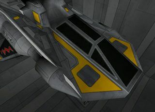
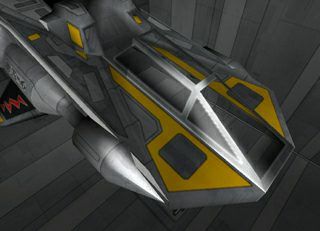
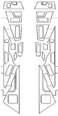
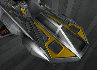
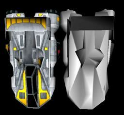
Some examples .... Imagine having a ship containing a lot of materials
(and a lot of texture). Now let's say you want to assign an envmapping
(cubemapping. if defined, is automatically applyied in place of the
standard envmap) to the right and left engine and to the cockpit. These
objects are covered by the textures ENGINE.TGA
and COCKPIT.TGA
(the object will look as the one in the left image, below)
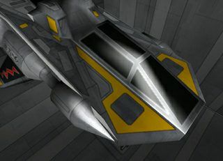
If you create two textures named ENGINE_ENV.PNG
and COCKPIT_ENV.PNG
(actually the same, i.e. the middle image), the result will look as the
image on the right.
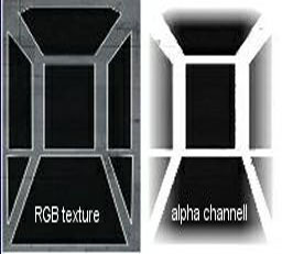
Now suppose I wanna apply transparency
to cockpit.
Transparencies are NOT represented by another texture but are within the
same texture, so I open COCKPIT.PNG
with an image editor (let's say Photoshop or GIMP), and add an alpha
channel. This specific, gray-scaled channel represents transparency.
Solid white means opaque, and solid black is fully transparent,
fading from black to white simulates different degree of transparency -
as an example, in the textures below I added some white to the border to
simulate a dirty effect on the glass (the granular spray tool will do
this nicely):
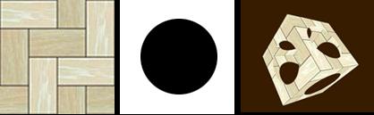
We can use this effect in a creative manner. For example: transparency is not just useful with glass objects, but also for defining fences or complex structures, (such as trees, fences, metallic carpentry etc) by just using a flat surface and a transparency texture:
Please note Chimera contains an automatic "alpha
tester" for sorting alpha object.
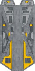
Now we want to apply bumpmapping to the central
surface.
Bumpmaps require an active light
to work, but we already have a light active, so if the base texture is
this BODY.TGA
(second image) we can create a grayscaled texture calling it
BODY_BUMP..PNG (third image)and the
result will look as the image on the right:
Now about glows or "lightmaps": a lightmap is a
secondary texture applied to the base texture to define the level of
brightness and color of the base texture.
The object ID lightmap(0/1)
statement controls the blend mode of the lightmap, in the default mode
"black" is trasparent and the lightmap increases the brightess of the
main texture, in the alternate mode the lightmap "darkens" the main
texture to produce dark, shadowed zones (this is the common trick used
by the 99% of the games to show complex but static shadows in the main
ambient, for example the classic light filtering thru the steps of a
stairway).
The engine can apply also a glow effect on
these lightmaps, to enhance quality.
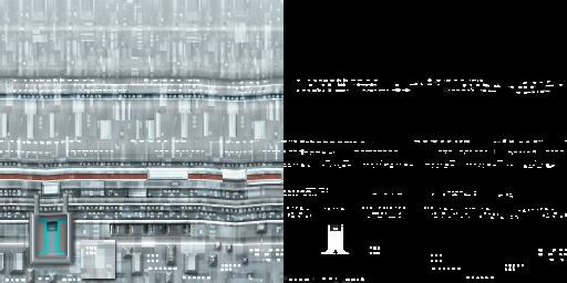
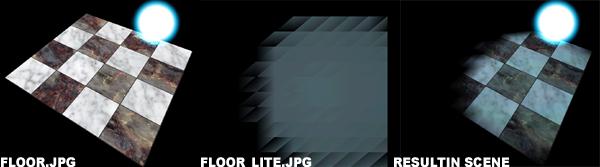
Let's consider my loved stardock: on the left there is the base texture
BASE.JPG, on the
right is BASE_LITE.JPG
(the same texture, this time processed by altering the contrast and
brightness of the first one):
the lightmap colorizes the base texture
and is NOT affected by lighting.
In the default mode the result is (see images below): in the left
image the base texture with a soft light coming from the left; in
the second image just the lightmap, in the third image the
two textures are blended together (notice the "windows" are lighted in
the dark side), in the fourth image the effect is optionally enhanced
with the fullscreen glow
effect

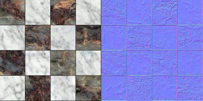
Now about dot3 bump mapping (or "tangent space bump") and specular bump mapping: they require an active light to work and vertex program enabled on your board, if the base texture is this MARBLE.PNG (image on the left) we can create a normalized texture calling it MARBLE_NORMAL.x or MARBLE_SPECULAR.x (image on the right, note: "_normal" and "_specular" are only naming convention to achieve the proper effect, the normalized texture is the same):
here the result: the first image on the left is the base scene, the middle image (dot3 bump mapping) is obtained with the normalized MARBLE_NORMAL.x and the image on the right (specular bump mapping) is obtained renaming the normal texture in MARBLE_SPECULAR.x :
There are a lot of tools helping you
create the normalized map, the previous sample was created with the
NormalMapFilter, a Photoshop plugin made freely downloadable from
nVidia
web site.
For OS X you can also use my free NormalMapGenerator software, in Misc
Stuff section of my website.
You can also assign a "moving"
multitexture (like an AVI) and make it "play" on a material: this is a
textgfx effect,
applied after the object is loaded.
Static shadows and lightmaps can be generated by the
internal radiosity processor.
See also
vertex programs about texture
effects.
To implement dynamic shadows you need a
light and an object casting shadow (duh!), two or more lights produce
two or more shadows.
The target object and the "fake" (the shadow caster, can be the same
object) object are defined into costructor (see sample).
Basic statements are:
| ID = new cShadow (0) | ||
|
||
| shadow ID
setlen(p1) |
"len" is the shadow volume lenght (default 100) | |
| shadow ID
nolight(p1) |
cast a shadow with or without a light enabled |
|
| shadow ID volume(p1) | shadow show or hide the entire volume
projected (not only the flat shadow), useful for "rays" effect |
|
| shadow ID active(p1) | enable/disable shadows on object ID | |
| shadow ID color (r,g,b,a) | set the shadow color (rgb) and transparency (a) | |
| shadow IDdefobj(obj1,obj2) | set
the master object 1 and the "fake" object 2 |
/* oad an object */
CUBE = load("CUBE");
object CUBE active(1);
/* load ship */
SR4 = load("SR4");
object SR4 active(1);
/* define a light */
LIT = new cLight(-1);
light LIT move(-500,0,-500);
light LIT active(1);
/* build the shadow class */
myShadow = new cShadow(0);
shadow myShadow
defobj(SR4,SR4);
shadow myShadow
color(0,0,0,0.8);
shadow myShadow
active(1);
scene start;
in this image: left standard shadow, middle
shadow with volume, right: shadow with volume and high color (1,1,1,1)
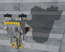
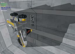
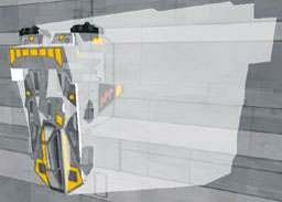
A little trick of the trade: because shadow implementation is very slow on old hardware, many games and demos do not calculate the shadow using the real object but using a simplified, invisible object. Consider these two models: the left one uses a good 2K poly resolution, the right object is the little brother, 400 poly and no texture, which is never put on screen but is used for shadow casting:
Chimera supports the use of "fake" objects for
shadows, in the first script you can add:
/* load fake/small ship */
SR4Fake = load("SR4Fake");
//load fake model
object SR4Fake active(0);
....
shadow myShadow
defobj(SR4,SR4Fake);
notice the fake ship is NOT active, and you DO NOT
need to reposition or rotation it in concert with the visible ship,as it
is all self-managed by the engine.
Static shadows can be generated by the internal radiosity
processor.
//TODO : Chimera supports also PCF Shadow Mapping :)

| ID = new cGlow() | create
a texture effect on the fly |
| delete cGlow(ID) | delete a texture effect |
| glow ID active(0/1) | enable
(1) or disable(0) |
| glow ID color(r,g,b,a) | assign
the RGBA value |
| glow ID
settings(p1,p2,p3) |
|
| glow ID
numelems(p1) |
|
| glow ID
offset (p1) |
simple sample of activating a glow (once, since is a
fullscreen effect)
myGlow = new cGlow(0);
glow myGlow settings(512,2,2);
glow myGlow color(0.6,0.6,0.6,0.6);
glow myGlow active(1);
Fullscreen lightbloom (or "bloom") is a cool effects
to enhance the lighting quality of the scene.
Lightbloom enhance the lighted areas with a photorealistic diffuse glow,
this effect do not requires any texture to works, the work is
indipendent from the number of polygons.

| ID = new cBloom() | create
a texture effect on the fly |
| delete cBloom(ID) | delete a texture effect |
| bloom ID active(0/1) | enable
(1) or disable(0) |
| bloom ID color(r,g,b,a) | assign
the RGBA value |
| bloom
ID fullscreen(p1) |
|
| bloom
ID settings(p1,p2,p3) |
|
| bloom
ID numelems(p1) |
|
| bloom
ID offset(p1) |
simple sample of activating a lightbloom (once, since is a fullscreen effect)
Blur is the standard effect to create "trails" using
multiple images/buffer overimposed, its used for "speed" effect and
more.
Like the glow and the bloom is a fullscreen effect so all the scene is
included and do not requires special parameters.
| ID = new cBlur() | create
a texture effect on the fly |
| delete cBlur(ID) | delete a texture effect |
| blur ID active(0/1) | enable
(1) or disable(0) |
| blur ID color(r,g,b,a) | assign
the RGBA value |
| blur
ID duration(p1) |
set the
persistence |
| blur
ID scale(p1,p2) |
simple sample of activating a lightbloom (once, since is a fullscreen effect)
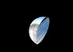
Real-time CSG is a cool feature that enables dynamic
addition and subtraction between two solid objects.
Like shadow-casting, it is a bit heavy for old hardware so ... use them,
if possibile, with low-poly count objects.
| ID = new cCSG (0) | create
a texture effect on the fly |
|
| delete cCSG(ID) | delete a texture effect | |
| CSG ID active(0/1) | enable
(1) or disable(0) |
|
| CSG
ID opmode(p1) |
add or
subtract |
|
| CSG
ID object1(obj_id) |
||
|
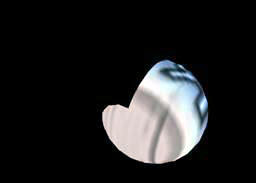
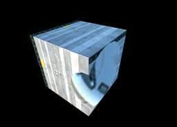
we load two intersecting object, a CUBE and a BALL, and a light just for fun:
LIT = new cLight(-1);
light LIT move(1000,0,0);
light LIT active(1);
CUBE = load("CUBE");
object CUBE move(-10,0,0); //moves to intersect BALL
object CUBE lighted(1);
object CUBE active(1);
BALL = load("BALL ");
object BALL lighted(1);
object BALL move(10,0,0); //moves to intersect CUBE
object BALL active(1);
myCSG = new cBlur(BALL,CUBE);
CSG myCSG
opmode(0);
CSG myCSG
object1(BALL);
CSG myCSG
object1(CUBE);
CSG myCSG
active(1);
scene start;
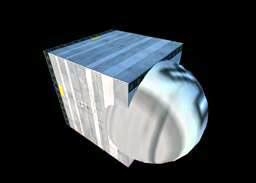
with CSG operations we have three possibility (from
left to right):
CSG myCSG
object1(BALL);
CSG myCSG
object2(CUBE);
CSG myCSG
opmode(0);
CSG myCSG
object1(CUBE);
CSG myCSG
object2(BALL);
CSG myCSG
opmode(0);
CSG myCSG
object2(BALL);
CSG myCSG
opmode(1);
in the third example the operator creates the shared
volume between BALL and CUBE so the result is the same (by exchanging
object1 with object2)
Note that this is all in realtime, so if you
rotation the BALL or move the CUBE the resulting object is always the
result of the add/subtract operation.
texgfx is an operator to control texture
effects. For example texture scroll, multitexture and reflection effect.
It is possible to apply a tex effect on every object texture, supposing
the object has a texture already applied or, at least, defined texture
coordinates.
| ID = new cTexgfx(OBJ_ID) | create a texture effect on the fly and assign it to OBJ_ID |
| delete cTexgfx(ID) | delete a texture effect |
| texgfx ID active(0/1) | enable (1) or disable(0) the ID operation |
| texgfx ID defobj(obj,subobj,material) | assign
the desired effect on an object <obj>, sub-object
<subobj> and material <material>. <obj> is the
object identifier returned by new, the other two are defined in
the object structure itself. You can also read the the
DEBUG.TXT file where subobjects and materials are listed; |
SCROLL
Move a texture on a material
| texgfx ID shift(x,y,speed) | Scrolls
the texture assigned to a material (see "assign") by <x,y>
steps in <speed> milliseconds note: <steps> must be in range from 0 (no movement) to 1 (movement by the size of texture) for example 0.5 means the texture scroll for half his size |
this is a sample code from the Horizon2 scene, we set a random shift over previously loaded cloud_object object
cShift = new cTexgfx(cloud_object);
texgfx cShift assign(cloud_object,0,0);
texgfx cShift shift(0,random(0,1000)/100000,10);
//this shift ranges from 0 to 0.001 every 10 milliseconds
texgfx cShift active(1);
MULTITEXTURE
Assigns one or more new texture(s) to a material and
changes it periodically:
| texgfx ID addtex(TEX_ID) | You can assign more than one texture and change them at regular intervals |
| texgfx ID change(speed) | To change the textures every <speed> milliseconds |
| texgfx ID target(textureType) | assign
the desired effect on a specific texture type
<ttextureTypes>, corresponding effect are: 0 = the effect replace the main texture 1 = the effect replace the envmap texture (imagine the envmapped "fire" onto the OneRing...) 2 = the effect replace the lightmap texture (it can be used for illumination) 3 = the effect replace the bumpmap texture (not really useful) |
this is a sample code from Horizon2 scene, after loading 30 textures we set a random change every "random" milliseconds:
totTex = 30;
tex0 = load("tex0");
load("tex1");
load("tex2");
......
load("tex30");
Rotor = new cTexgfx(cloud_object);
texgfx Rotor
assign(cloud_object,0,0);
//assign the "rotor" effect to object "cloud_object", object 0 material
0
for (t=0;t<totTex;t++)
texgfx Rotor texture(tex0 +
t);
//assign
texture from n to n+30
texgfx Rotor
change(random(2000,8000));
//assign random change time
texgfx Rotor active(1);
REFLECTIONS
A texture can be used as a secondary
picture of the scene. This kind of texture is created on the fly and
applied to an object and requires a "virtual" camera, positioned where
you want, to take shots of the scene and transferred to the texture, so
you can simulate reflections, picture-in-picture or external screens,
etc
| texgfx ID position(x,y,z) | camera
position note: if the target is the cubemap (999) the correct values are: (0,0,0) = ignored, cubemap is taked from the center of the object; (-1 or +1,-1 or +1,-1 or +1) = the camera position is "mirrored" onto the specifyied plane for correct reflection (for example a water surface must have (0,-1,0) where the reflected cubemap is taken from opposite camera y position) |
| texgfx ID angle(x,y,z) | camera
rotation note: if the target is the cubemap (999) this statement is ignored |
| texgfx ID reflect(speed,future,angle) | enable
shots. Shots are taken every <speed> millisecond (I suggest
you to leave this value as high as possible, because taking a shot
is time consuming). The shot is taken at current texture
resolution so the larger is, the higher the shot resolution is,
and the more time consuming the process will be. The shot is taken using a field of view by <angle> degrees. Pass 0 to future By default leave angle = -1 (in this case the engine use the current field of view), if the target is the cubemap (999) this parameter is ignored |
| texgfx ID target(textureType) | assign
the desired effect on a specific texture type, textureTypes and
corresponding effect are: 0 = the effect replace the main texture 1 = the effect replace the envmap texture (imagine the envmapped "fire" onto the One Ring...) 2 = the effect replace the lightmap texture (it can be used for illumination) 3 = the effect replace the bumpmap texture (not really useful) 999=all the environment is reflected onto the cubemap (the general cubemap or the object's cubemap if defined) |
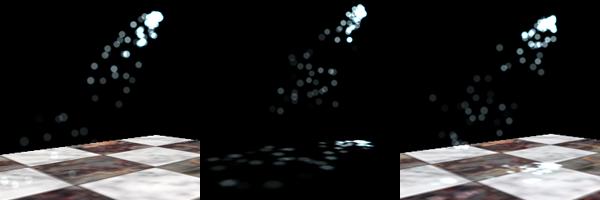
the kind of texture to be replaced can be defined with the target statement: the first image from the left is the original scene, in the second image the particle is reflected onto the primary texture, in the third image the reflection is mapped onto the lightmap (secondary) texture:
reFlect = new cTexgfx(FLOOR);
texgfx reFlect move(0,-200,0); //reflect the scene
from the following angle and position:
texgfx reFlect angle(90,0,0);
texgfx reFlect reflect(20,0,-1);
texgfx reFlect
target(0);
//the
reflection replaces the lightmap (like a light)
texgfx reFlect active(1);
Its also possible to map the surrounding environment straight to the cubemap (a standard cubemap must be present):
scene tfilter(3);
scene cubemap;
reFlect = new cTexgfx(Ball);
texgfx reFlect reflect(10,0,60); //in this case 60 is
ignored
texgfx reFlect target(999);
texgfx reFlect active(1);
To enable reflections over a secondary texture you
must avoid to use mipmapping filters in you
scene, use instead a
non mipmapped mode, for example:
scene tfilter(3); //bilinear
anisotropic
RADIO
The Chimera engine contains a lightmap generator
based on the Radiosity algorithm.
Radiosity assures the full handling of global illumination, shadows
generation and efficient light distribution but, like any other
raytracing legacy process, it is very slow (time heavily depends by the
numbers of vertices) and requires some attention to the parameters.
The process is completely driven by the script and can be used once
because the radio class -optionally- saves the generated lightmap
texture (the "lightmap" is a secondary lighting textures overlapping the
main texture, see the object
chapter about lighmaps) for every
object. This way when you launch the scene again you can use the
lightmap from the previously processed scene WITHOUT having the
radiosity processor redo all the calculations from start.
Take a look at the following images:
the one on the left is the original scene, in the
center a new image-file generated by the radiosity processor (managed by
the engine as a lightmap) , in the third image the resulting scene.
You may also disable saving the resulting lightmaps to disk and
make a scene with interactive calculation every launch.
It's important to understand that Radiosity DOES NOT HANDLE point
lights (i.e. invisible light sources): EVERY object, particle, flare in
the scene works as a light source, ok it seems absurd but it's amazing:
imagine a scene where all object are subjected to illumination and
a circle of particles is dancing in the middle of the scene, or with a
simple skybox outside the window... then all the objects are lighted by
all these "light" sources, with corresponding colors and level!
Another example: a dark alley with dark windows: place a lightmaps on
these windows (so they seems lighted) and place a flare on a street
lamp, both flare and lighted windows act as lights brighting the scene
and making proper shadows!
In short, in building a scene to be rendered with the Radiosity
algorithm, keep in mind the following :
- disable (or delete) any "real" realtime "opengl" point
light (do noth bother
too much with this...the radio process does this automatically);
- put the "ok, I'm lighted" flag on every object you want to be part of
the radiosity lighting process (eg.: object
myFloor lighted(1) );
- put the "ok, I'm NOT lighted so I AM a
light" flag on every object you want to act as light source (eg.:
object myNeonPanel lighted(0) ... object myMoonSphere lighted(0)
);
OR:
- create flares or particles (flares and particles cannot be "lighted"
so they always act as a light source)
or eventually both the solutions.
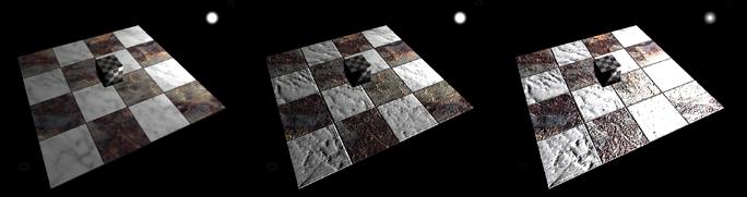
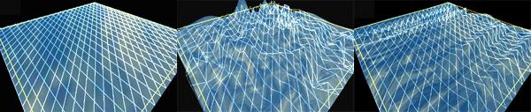
To obtain the best results there are two concept to understand: the polygon
subdivision and the number of the passes of the rendering.
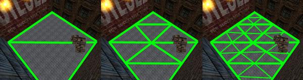
Polygon subdivision represent the precision level of the
resulting render. Since the process works with vertices is important to
"slice" large polygons in several smaller polygons to improve precision
(and slow render time) ... ok ... imagine to have a floor made by two
triangles (see image on the left, below).
That floor is too simple to cast shadows behind the wooden boxes because
in the "box zone" there is just a sigle vertex, its possible to improve
the object with a level 2 subdivision (the image on the center) or
a level 3 subdivision (image on the right). Every level splits any
triangle in four triangles.
The subdivision level depends from the complexity of the object itself.
In the statement table there are a couple of statements regarding
general subdivision or specific object subdivision.
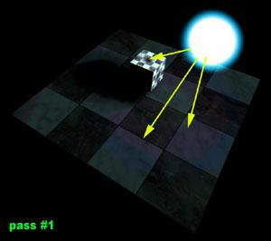
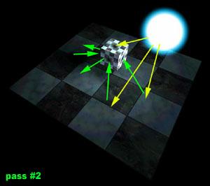
About rendering passes: the
lenght of rendering loop (how many passes) depends after all on how much
you are satisfied by the scene.
Usually Radiosity requires several passes to "work" really as a true
radiosity process. Take a look at the following image: in the first
passage Radiosity calculates the illumination level straight from light
to object (first image on the left, notice the hard shadows and low
level of illumination of the floor and the cube), THEN, in the second
pass, every object accumulates light from the surrounding objects
(please note that, in the right image, that the shadow is softer and the
floor acquires illumination from the cube, and vice versa):
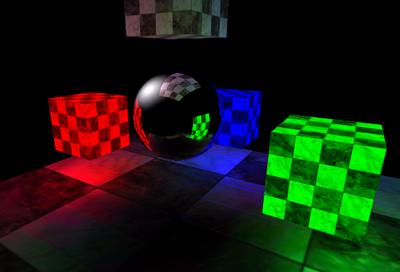
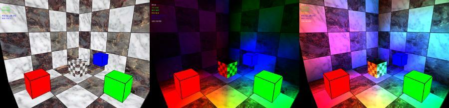
Another example, this time with
coloured light sources:
left image: in the original scene there are three unlighted
objects- a red cube, a blue cube and a green cube working as lights;
middle image: the scene after one rendering pass: the walls and the
middle cube are lighted by the three cubes;
right image: walls, floor and the middle cube interact with the color of
each other doing a correct diffuse lighting.
radiosity class basic statements are:
| ID = new cRadio(-1) | allocate the new radiosity process |
| delete cRadio(-1) | delete the radiosity process ID (only one process at a time is supported) |
| radio
calc |
begin the radiosity process |
optional parameters (to call BEFORE the begin process) are:
| radio litpower(light_multiplier) | (0-255, by default 1) increase or decrease the brightness of lights, reducing the required number of passes |
| radio lmsize(texture_size) | (by default 256) set the size (in pixels) of the resulting generated lightmaps |
| radio scrsize(buffer_size) | (by default 128) set the offscreen buffer size for calculations, bigger is slower but more precise, smaller is fastest |
| radio savemode(0/1) | (by
default 1=on) save the lightmaps on the disk (1) or dont save the
lightmaps (0) - use 0 to test if the scene is lightmapped correctly ... until you decide to exit, very useful during testing renders |
| radio
lmangle(degrees) radio lmoangle(OBJECT_ID,degrees) |
(by
default 120) set the acceptable incident angle for all the object
present in the scene some materials may require a narrow angle (for example 60 or 90 works good with metal materials) if you want to specity angle for specific material use lmoangle: it's the same as lmangle but specify angle only for an object, eg.: radio myRad lmoangle(myShip,60) |
| radio
polydiv(subdivision_level) radio polyodiv(OBJECT_ID, subdivision_level) |
(by
default 1 = no recursion) sets the subdivision level for all the
object of the scene, every increase of level increases rendering
time exponentially by a power of three , since every
triangle is splitted in other four triangles: in a scene
with a rectangular floor made with two triangles, polydiv(1)
processes the original 2 triangles, polydiv(2) treats them as 8
triangles, polydiv(3) treats them as 32 triangles and so on; polyodiv is the same statement but refers to an object only, if you imagine a well built scene with decent (i.e. high polygon count) objects and a poor two-triangle floor, you can enhance just the floor only using, for example: radio myRadio polydiv(1); radio myRadio polydiv(poorFloor,3); |
| radio lowshadow(brightness_level) radio darklevel(brightness_level) |
(0-255,
by default 0 ) ok, these (equivalent) statements dont not sound
like a serious radiosity but ... c'mon, really do you want to wait
helplessly as the process runs for hours? :-) anyway ...values
under "brightness level" are untouched by the light multiplier,
helping in shortening the process by maintaining the shadows at
the "proper" darkness despite using a high value of lightpower to
get decent results in a few passes. Maybe sounds difficult but it's really simple: just imagine the litpower acting like a brightness control forcing the light to saturate the scene without waiting hours,the darklevel works a bit like a saturation/contrast treshold, darkening and maintaining the dark zone; finally .... these parameters are stricly optional |
| radio texreset | resets all lightmaps, useful only for long, repeated processes in a scene |
| LAMBERT.PNG | optionally
you can use a texture with alpha channel, named
LAMBERT.TGA, as a filter for surface
incident light. If the file is present in the data folder everything is completely selfmanaged by the radio process. There are some example files of this texture in the SDK |
the shortest script to achieve radiosity is, for example:
myObj = new
("damned_alley"); //load some
object
.....
streetLamps =
new(...);
//load
some flare
....
scene start;
.....
new cRadio(-1);
radio begin;
delete cRadio;
in this mode (without parameters) the
engine automatically saves the lightmaps in the data folder (take a
look, you must have a damned_alley_00_lit.tga
file).
Multiple passages can ben done simply using the script syntax, for
example you can do a three pass render with:
pass = 3;
while(pass > 0)
{
new cRadio(-1);
radio begin;
delete cRadio;
pass--;
}
now, something more complex to produce the
four scene pass in the image:
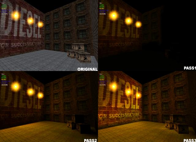
backyard =
load("walls");
//load the objects and
object backyard
lighted(1);
//..specify they are to be lighted
....
woodenboxes = load("box");
object woodenboxes lighted(1);
....
simplefloor = load("floor");
object simplefloor lighted(1);
....
posterflares = new
cFlare(-1); //load the flares
and put these onto the wall poster (no, I'm not sponsored by Diesel
Jeans (tm) :-)
....
dklevel =
1;
//sets
the dark level untouched by light multiplier
litpowa =
10;
//sets
the initial light multiplier
iterator =
4;
//sets
four pass render
while(iterator > 0)
{
new
cRadio(-1);
//create
process
radio
lowshadow(dklevel);
//sets the dark level
radio
polydiv(1);
//leave
the original polygon subdivision
radio polyodiv(simplefloor ,3);
//...except for floor, it's a simple object so we can split it in 32
triangles
radio
litpower(litpowa);
//sets the light power multiplier
radio
lmsize(256);
//sets
the size of the lightmaps (256x256 pixels)
radio
lmangle(160);
//sets
the light angle for all the object
radio lmoangle(simplefloor
,110); //....expect for floor, we want it
more reflective
radio
savemode(1);
//instruct
the process to do a save of the lightmaps at the end of the process
radio
begin;
//start
the process
delete
cRadio;
//when
done it clears the memory
iterator--;
//pass
-1
litpowa =
1;
//reset
the lightpower (because from the second pass there is more "light"
around)
( .... and back to the top for another
pass ... )
}
Water surfaces are controlled by the
properties of the water operator.
This effect is applicable on an object's surface, and these surfaces
must be defined in a object.
For example, you can easily create a landscape, and a "sea" as a
sub-object, represented by a plane (in 3DStudio), or a grid of vertices
(25x25 is enough).
Then we apply the water effect on this "sea".
If you hate prebuilded waves and want more customization use the
fluide
operator.
| ID = new cWater(OBJ_ID) | create a water effect on the fly, and assign it to object (OBJ_ID), assuming subobject (0) |
| delete cWater(ID) | delete a water effect |
| water ID active(0/1) | enable (1) or disable(0) the water effect |
| water ID object(obj subobj) | assign
the effect on object (obj), subobject (subobj) same as texgfx or other operators, the full list of object / materials can be found in DEBUG.TXT |
| water ID speed (refresh,impulse) | specify the refresh speed of wave (by default 10ms) and the impulse speed (default 10ms), "impulse" specifies the time elapsed from one wave creation to the next |
| water ID wave(waveType,waveHeight,waveForce) | specify
type of wave.waveType can be set to: 0 = hill wave - a bump moving in the "sea" 1 = linear wave - a wave which goes from side to side of the "sea" 2 = point wave - e.g. that caused by a raindrop in the "sea" waveHeight is the max height of wave (default=30) waveForce is a fine trim and by default leave 0.02 |
| water ID coord(x,y) | other
than "wave" you can specify the exact coordinates where wave is
generated, useful for "driven" surfaces, so you can generate a
wave in the place where a drop is falling etc.etc., NOTE: (x,y) represent the rows and columns of your grid, NOT the real spatial coordinates !! |
| water ID sorttriangles | may help with misaligned objects |
left image: original object - center: hill random wave - right: linear
wave
this snippet is taken from the "Distant Shores" scene, it loads a grid and enable the water fx on it:
//load sea surface
SEA = load("seaplane2");
object SEA scale(80000);
object SEA move(+740,-1000,+700);
object SEA rotation(-180,0,0);
object SEA diffuse(1,1,1);
object SEA active(1);
object SEA fog(1);
//add water effect to SEA object
H2O = new cWater(SEA);
water H2O speed (50,10);
water H2O wave(0,2,0.02); //"hill" wave, 2 is a very
low height (and 0.02 is the default force trimmer)
water H2O active(1);
Fluide surfaces are
controlled by the properties of the fluide
operator (similar to water operator, but with more handling parameters).
This effect is applicable on an object's surface, and these surfaces
must be defined in a object.
For example, you can easily create a landscape, and a "sea" as a
sub-object, represented by a plane (in 3DStudio), or a grid of vertices
(25x25 is enough).
Then we apply the fluide effect on this "sea",
| ID = new cFluide(OBJ_ID) | create a fluide effect on the fly, and assign it to object (OBJ_ID), assuming subobject (0) |
| delete cFluide(ID) | delete a fluide effect |
| fluide ID active(0/1) | enable (1) or disable(0) the fluide effect |
| fluide ID defobj(obj subobj) | assign
the effect on object (obj), subobject (subobj) same as texgfx or other operators, the full list of object / materials can be found in DEBUG.TXT |
| fluide ID speed (refresh) | specify the refresh speed of the fluide (by default 10ms) |
| fluide ID addimpulse (row,col,amplitude,frequency) | enable
an "oscillator" on row,col with amplitude (by default 40.0) and
frequency (by default 20.0) amplitude and frequency depends of the size of the target object NOTE: (x,y) represent the rows and columns of your grid, NOT the real spatial coordinates !! |
| fluide ID addperturb (row,col, height) | change
the height of a vertex, nearby vertices respond accordly, this is
a simplifyed form of addimpulse
where the surface if perturbed without using an oscillator (eg.:
using a for loop with addperturb to create rain effect) NOTE: (x,y) represent the rows and columns of your grid, NOT the real spatial coordinates !! |
| fluide ID duration(time) | specify life (in ms) of the oscillator, by default 2 seconds (2000 ms) |
| fluide
ID wavetime(n) fluide ID waveweight(n) |
a
couple of fine tuning parameters: wavetime (by default 0.004) represent the "fluidity" or speed of the surface; waveweight (by default 0.0002) the "weight" or the force of the oscillator |
| fluide ID sortfaces | may help with misaligned objects |
| fluide ID update |
this snippet is taken from the "MoonBay" scene, it loads a grid and enable the fluide fx on it:
//load sea surface
wSurface= load("seaplane2");
.....
//add water effect to wSurface object
myPerturb = new cFluide(wSurface);
fluide myPerturb assign(wSurface,0);
fluide myPerturb speed (10);
fluide myPerturb wavetime(0.001);
fluide myPerturb addimpulse (50,50,2,100);
fluide myPerturb active(1);
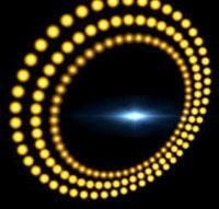
Flare
class controls the properties of flares - i.e. lighting textures.
Members of the flare class can be used to create light effects
such as lamps, sunlight, lens flares, etc.
Flares are either linked to the vertex of an object (e.g. a jet engine)
OR freely positioned in your screen, independent from any object
independent.
You can use a single flare to create all the lights on an object -
engines, navigation lights, cockpit lights and so on, or use multiple
emitters from a single flare class (i.e. having the same look) to define
each light.
Flares can use more than one texture, and textures can be swapped at
specified intervals, to simulate light flashing and so on.
You can also cast an automatic (but customizable) "lens flare" from the
same emitter.
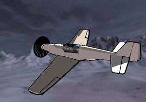
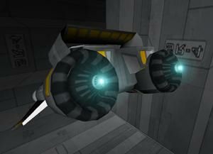
In the example below, the engine glow is made using a single flare class
with two emitters, appended to two object vertices - the engine nozzles:
| ID = new cFlare(OBJ_ID) | create a flare on the fly and assign it to OBJ_ID or standalone flare if OBJ_ID=-1 |
| delete cFlare(ID); | delete a flare |
| flare ID active(0/1) | enable (1) or disable(0) the ID drawing |
| flare ID test(testtype) | set
the current depth test for this flare and its emitters. testtype
can be: 0=no test, flare is always visible 1=standard depth test, flare is partially occluded by object and doesn't fade 2=flare is not occluded by the object as long as the center is visible, then fades when occluded with a cool effect (as in the Unreal(tm) FPS); |
| flare ID speed(10) | used if test=2 (occlusion flare) to specify the fader time in millisecond |
| flare ID color(r,g,b,a) | set flare color, usually leave this at 1,1,1,1 (default) and use the texture colors |
| flare ID size(size) | set the size of the flare |
| flare ID texture(TEXTURE_ID) | load texture <texturename> , you can specify multiple load to obtain multitexture |
| flare ID change(speed) | set <speed> for texture change, only if you have defined more than one texture for a flare |
now the flare can be "appended" to an object vertex or it can be standalone (sun etc.)
| flare ID position(x,y,z) | only for standalone flares: position a standalone flare to (x,y,z) coords |
| flare ID add(obj,sub,vertex) | link
flare on a vertex, "move" is unused in this case because flare is
assumed to be updated by the coords of the vertex accordly with
the object, parameters are: OBJECT (the ID you are using for an object) SUBOBJECT (number, related to object structure) the vertex of this subobject You can check the subobject id and vertex id by pressing "1" or "2" on the keyboard and verify the object structure thru the usual DEBUG.FILE You can read also the DEBUG.TXT file where subobjects and materials are listed; |
| flare ID offset(emitter,x,y,z); | set an offset for an <emitter>. The emitter is in local space and if already related to an object where flare is linked, this statement is ignored if flare is standalone |
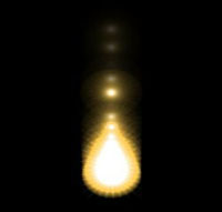
Some examples....
How to create a distant sun:
SUN = new cFlare(-1);
flare SUN texture(load("SUN"));
flare SUN move(14500,-16000,+500);
flare SUN size(10);
flare SUN speed(10);
flare SUN color (1,1,1,1);
flare SUN active(1);
How to put engine flares, then flashing lights onto a starship, using three textures:


/**************** load the object
***************/
SHIP = load("starship");
object SHIP active(1);
obj_engine = 0;
/****************engine flares ***************/
ENGINES = new cFlare(SHIP);
flare ENGINES texture(load("FLARE_BIG");
flare ENGINES add(SHIP, obj_engine, 20); //add emitter
to vertex #20
flare ENGINES add(SHIP, obj_engine, 57); //add emitter
to vertex #57
flare ENGINES
offset(0,1,0,0);
//light
offset otherwise flare is "in" the model
flare ENGINES offset(0,1,0,0);
flare ENGINES active(1);
/****************positional lights ***************/
LITPOS = new cFlare(SHIP);
flare LITPOS texture(load("FLARE_BIG"));
flare LITPOS texture(load("FLARE_MEDIUM"));
flare LITPOS texture(load("FLARE_SMALL"));
flare LITPOS size(1);
flare LITPOS test(2);
flare LITPOS
change(50);
//flare cycle from big to small every 50 ms
flare LITPOS add(SHIP,31,1032); // notice a single
LITPOS can be used for three lights
flare LITPOS add(SHIP,31,1214);
flare LITPOS add(SHIP,79,204);
flare LITPOS offset(0,-1,0,0);
flare LITPOS offset(1,+1,0,0);
flare LITPOS offset(2,-1,-1,0);
flare LITPOS active(1);
Flares can be linked to an object vertex. If you plan to move a set of flares thru keyframer, you must create a hidden object (a triangle is ok), then apply keyframer onto this object, and use the same fake object to generate particles.
LENSFLARE
A "lensflare" can be appended to the same emitter of the flare, for
the lensflare you do not need to specify a texture because sets of
lensflare are already defined for your convenience, it's also possibile
to set the "brightness" of the screen when the camera is looking in the
flare direction (sunlight effect), Here is a visual of a lensflare
appended to the a flare emitter (the cyan one, see previous image)
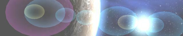
| flare ID lens(size,bright,shape,filled) | use
this statement to add a lens-flare to a standard flare. Lens
flares are calculated and do not require textures. The parameters
are: <size> the size of the components <bright> the level of brightness cast on the screen when a flare is pointing toward the camera (set to "0" if you dont want this effect) <shape> is the number of sides for the lensflare component, for example "6" to draw a series of hexagons, so the more <shape>,the more lens flares are rounded <filled> is how the flare is drawn. "0" is not filled, so the flare is empty with borders, "1" is the opposite. |
| flare ID set(numSet) | select
a <numSet> set of lens-flares (by default set "0" is used).
There are some (4) separate sets of flares, in different colors
and shapes (see below), and more are to come in future versions! |
the "distant sun" code is now:
SUN = new cFlare(-1);
flare SUN texture(load("SUN"));
flare SUN move(14500,-16000,+500);
flare SUN size(10);
flare SUN speed(10);
flare SUN
set(0);
//choose
the flareset
flare SUN lens (0.6,0.8,12,0); //modify some parameters...
flare SUN color (1,1,1,1); //this is
ignored except for flareset #3
flare SUN active(1);
let's analyze the parameters: flare ID set(0...5) use predefined flare set n, ranging from 0 to 5 (for now), indicatively these sets are (from 0 to 5):
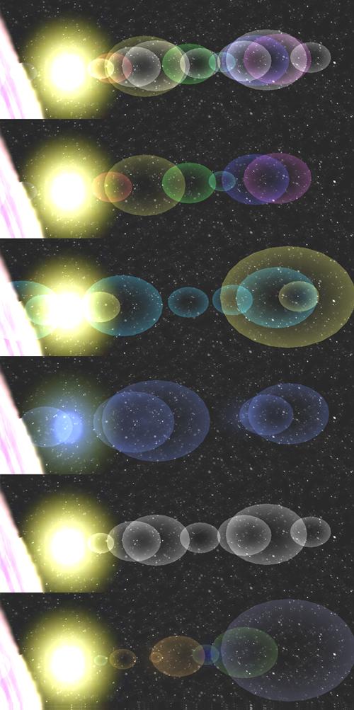
Please note that flareset #3 (in blue
in the upper image) is a special set of flares, which doesn't use the
preset colors but a color set defined by user.
To produce the following flare just pass flare
SUN color (1,1,0,1);

As a first parameter of flare
SUN lens (0.6,0,12,1) we
have the dimension of the flare, and this depends from the scene.
The second parameter of flare SUN lens
(0.6,0,12,1) defines the brightness of flare
(when observer "looks" in the flare direction), this is the difference
between
flare SUN lens (0.6,0,24,0)
(in the previous image) and flare SUN lens
(0.6,0.8,24,0) below:
the third parameter of flare
SUN lens (0.6,0,24,0) defines the number of
sides of the flare, this is the difference between
flare SUN lens (0.6,0,24,0)
(below, first image) and flare SUN lens
(0.6,0,6,0) (below, second image):
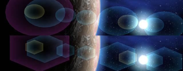
the last parameter of flare
SUN lens (0.6,0,24,0) defines if flare must
be filled or not, this is the difference between
flare SUN lens (0.6,0,24,0)
(below, first image) and flare SUN lens
(0.6,0,24,1) (below, second image):
particle statements control the properties of
particle systems.
Particle systems can be dynamic or static, generated by spare points or
from an object's vertex, and point-defined or volume defined.
Like flare
particle system can be
linked to an object vertex or leave alone, a single system can use more
than one emitter.
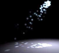
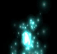
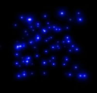
Some visual examples (from left to right):
standalone particle system, generated from a point, with all-axis random
acceleration;
standalone particle system, generated from a point, with Y vertical
acceleration;
standalone particle system, generated in a a defined area (and not from
a point);
Particle systems linked to an object
can act both in LOCAL and WORLD space. Local space means that particle
generation, distribution and movement are relative to object
orientation, and in global space are relative to "real" world
orientation. For example, looking at the flare
sample, appending a single particle system to a ship, and defining two
emitters related to the two engine ship is a nice way to simulate gas
exhaust... then if you move the ship, if the PS (particle system) is in
local space, gas is coherent with the ship and will rotation with it,
while in world space the PS leaves trails (altough is always fixed to
the vertices).
PS's are dynamic by default (because they are used largely for
simulating dynamic entities like fire) but you can "freeze" them, just
in case you need say, a galaxy... ;)
| ID = new cParticle(OBJ_ID) | create a particle system on the fly and assign it to OBJ_ID or standalone if OBJ_ID=-1 |
| delete cParticle(ID) | delete a particle system |
| particle ID active(0/1) | enable (1) or disable(0) the ID drawing |
| particle ID total(tot) | defines a PS to manage (tot) particles at a time, with multiple emitters. This number is shared evenly between emitters (e.g. 300 particles with 3 emitters, every emitter will generate 100 particles); |
| particle ID rgb1(r,g,b) | define the starting color of the particle, color will be interpolated between "life" |
| particle ID rgb2(r,g,b) | define the ending color of the particle, color will be interpolated between "life" |
| particle ID size(size) | define the size of the particle |
| particle ID test(testtype) | define the depth test for PS, 0=no test (always visible), 1=depth tested |
| particle ID blend(blendmode) | define
the color combine between particles: 1=(default) saturate: every particle add the color to other particles (eg: a fire effect) 0=opaque: every particle is "opaque" like objects (in this case only 32bit textures can define transparencies) |
| particle ID texture(TEX_ID); | assign texture TEX_ID to a PS (you can use load, eg.: particle Test texture(load("bigmesh")); |
| particle ID life(n) | define the mean life of a particle in <frames>, if you want to freeze use "dead" |
| particle ID dead(0/1) | define
static or dynamic PS: 0=frozen ("life" parameter is ignored) 1=dynamic, new particles are added as old particles die |
| particle ID direct(x,y,z) | define the direction vector for particle movement |
| particle ID accel(x,y,z); | define the acceleration vector for particle movement |
| particle ID radius(n) | define a general radius, representing the "spread" size of PS, the larger the more "spherical" the emission is |
| particle ID speed(n) | define the update timer (in ms) of the PS |
| particle ID volume(x,y,z) | define a volume containing particles, by default volume is equal to (0,0,0) so initially a PS has a single-point source, so by specifying "volume", you are instructing the engine to use a "box" as an emitter, instead of a point, so new particle are generated in random positions inside this "box" |
| particle ID casual(n) | use 0=rgb colors or 1=a random generated color at every particle created (in this case "rgb1" and "rgb2" will be ignored) |
| particle ID single(n,x,y,z) | position a single particle <n> at <x,y,z> coordinates (local or global, depending on the PS), see the last example for positioning a galaxy :-D |
For a particle system lnked to an object use:
| particle ID space(n) | defines
if a PS - linked to an object - will act in 0=local (the direction of emission is rigidly oriented with object) 1=world space (eg:: simulate exhaust trails ) a standalone PS ignores this parameter because it is always in world space |
| particle ID add(obj,sub,vertex) | like
for flares
this adds an emitter to an object <obj>, at sub-object
<sub>, and vertex <vertex>. You can check subobject
and vertex number with key "1" or "2" in Chimera. A PS can have multiple emitters, but properties (colors, dead etc) are applied to all the emitters of the PS. You can also read the DEBUG.TXT file where subobjects and materials are listed; |
| particle ID offset(emitter,x,y,z,) | like for flares this permanently moves an <emitter> by <x,y,z> from the current <obj, subobj, vertex> position |
Standalone (not object linked) particle system can use:
| particle ID position(x,y,z) | standalone PS: move the PS to <x,y,z> world coords (object-linked PS will use object position) |
| particle ID rotation(x,y,z) | standalone PS: rotation the PS by <x,y,z> angles (object-linked PS will use the object rotation) |
To create a single standard emitter:
FIRE = new cParticle(-1);
particle FIRE texture(load("SUN"));
particle FIRE move(14500,-16000,+500);
particle FIRE size(10);
particle FIRE rgb1(1,1,0.5,1); //set starting color to
yellow
particle FIRE rgb2(0,0,0,1); //set enging
color to black
particle FIRE active(1);
now add a slow movement on the Y axis
particle FIRE direct (0,0.2,0);
particle FIRE accel (0,0.2,0);
By now, tired of fire, we add this cool PS to the usual double-engine of the usual boring ship (the code is near the same as flares!!!):
SHIP = load("starship");
object SHIP active(1);
obj_engine = 0;
ENGINES = new cParticle(SHIP);
particle FIRE texture(load("FLARE_BIG");
particle FIRE add(SHIP, 0, 20); //add emitter to
vertex #20
particle FIRE add(SHIP, 0, 57); //add emitter to
vertex #57
particle FIRE offset(0,1,0,0);
particle FIRE offset(0,1,0,0);
particle FIRE active(1);
The next advanced example produces, thru simple
math, concentric waves of particles:
scene move (0,0,-160);
SYS = new cParticle(-1);
particle SYS texture(load("STAR"));
particle SYS total(250);
particle SYS size(5);
particle SYS rgb1(1,1,1);
particle SYS rgb2(1,1,1);
particle SYS dead(0);
particle SYS active(1);
dist = 8000;
rings = 5;
ringstar = 50;
dr = 1100/(rays-1);
n = 0;
for(ir=1; ir<=rings; ir++){
r = dist+(ir-1)*dr;
for(it=1; it<=100; it++){
t=n*6.283185308/ringstar;
particle SYS
single(n,r/100*cos(t),r/100*sin(t),0);
n++;
}
}
scene start;
while(1){
for (t=0;t<360;t+=0.01){ particle SYS
angle(t,t,t); }
}
As particle systems can be linked to an
object vertex, if you
plan to move a particle system thru keyframer,
you must create a hidden object (a triangle is ok), then apply keyframer
on that object.
light statements control the properties of
lights, i.e. the illumination level of the objects and the entire scene.
A "light" is an invisible entity (at least .... until you append a flare
;-) and in that case we can only decide the position and the colors, but
a light can also be "linked" to an object, like flares and particles, so
the best way to make moving dynamic lights is to link this entity to a
moving object.
NOTE: Although the Chimera engine has no light limit, some standard
openGL implementations do not support more than 8 lights.
| ID = new cLight(OBJ_ID) | create a light nd assign it to OBJ_ID or standalone light if OBJ_ID=-1 |
| delete cLight(ID) | delete a light; |
| light ID active(0/1) | activate (1) or deactivate (0) a light, If you want to kill a light only for a selected object use object OBJ_ID lighted(0); |
| light ID diffuse(r,g,b) | assign diffuse color (rgb) on light ID |
| light ID ambient(r,g,b) | assign ambient color (rgb) on light ID |
| light ID specular(r,g,b) | assign specular color (rgb) on light ID |
| light ID exponent(exp) | define spot exponent value |
| light ID cutoff(value) | define spot cutoff value |
| light ID attenuate(value) | define the attenuation factor for the light ID, without this value the light is (by default) infinite |
| light ID direction(rx,ry,rz) | define the direction of the light ID, without this value the light is (by default) omnidirectional |
like particles and flares the light can be positioned "stand alone" or attached to a moving or still object:
| light ID position(x,y,z) | move the light ID to position (x,y,z) |
| light ID object(OBJ_ID) | assign light to object (OBJ_ID) so light moves accordly |
Important notes about lights:
- Light controls bump-mapping
and shadows,
without light these effects are disabled;
- Shadows
are cast by ALL lights defined, be aware that too many lights casting
shadows slow down the scene;
- Bump-mapping
depends from first light only;
- you can position a light with a keyframer
only by applying a keyframer on an object (visible or invisible) and
linking the light to the object.
//TODO : Chimera supports now Volumetric Light /
Light Scattering and the usual "GodsRays" coming from a single obiect
skybox statements controls the
appearance of the skybox , i.e. the background of the scene landscape,
There can be only one skybox at a time, but you can dynamically create
and dispose of them.
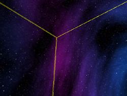
| new cSkybox | create a skybox object (please note no entity_id is returned...there's only one skybox at a time) |
| delete cSkybox | delete the skybox |
| skybox active(0/1) | activate (1) or deactivate (0) skybox drawing |
| skybox ("texname") | load
the skybox textures with name beginning with "texname" the disposition is the same as the real cubemap |
| skybox size(n) | set
the skybox size to (n) units. By default skybox is sized like the
scene
"far" parameter. Sizing skybox has no real value except to extend the "far" viewable area without cutting big objects, remember to extend the scene far limit according to the skybox (or viceversa) |
| skybox rotation(x,y,z); | rotation
the skybox by (x,y,z) degrees on a corresponding axis You can rotation a skybox continuously, to simulate, for example, a sunset, or you can rotation skybox to position a cubemap accordingly |
| skybox color(r,g,b) | sets
skybox color to (rgb) value, to simulate sunset and other
effects... |
to create a decent skybox, you must have six textures named "picname_xxx" where "xxx" is the orientation (left, top, right, bottom, front and back). For a skybox and a cubemap, for example SPACESTATION_FRONT.TGA and SPACESTATION_BOTTOM.JPG are both valid, the orientation follows the "standard" cubemap defined by nVidia in his demos
snippet from Night Fly scene:
scene
cubemap;
//enable and load cubemap reflections
SKY = new cSkybox;
skybox ("cubemap"); //skybox uses the same textures so
lanscape is coherent with reflected stuff
skybox rotation(0,0,0);
skybox active(1);
The keyframer (framer
in short) class is an abstract class that builds an interpolated path,
derived from a series of control positions.
The path can be assigned both to camera and objects, theoretically with
just 4 control points you can define a circular path.
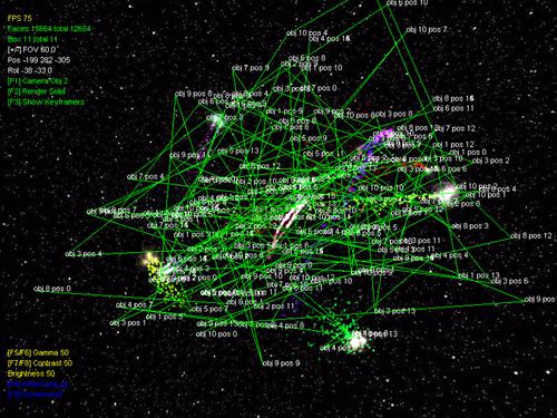
the keyframers used by stars from Stardance scene
(use V key in debug mode to display the keyframers)
| ID = new cFramer(OBJECT_ID) | create
a path on the fly this path will be assigned to object OBJECT_ID, or to the main camera if "-1" |
| delete cFramer(ID) | delete a path |
| framer ID active(0/1) | enable(1) or disable(0) the path (disabling stops camera or object) |
| framer
ID object(OBJECT_ID) |
assign a path to OBJECT_ID, or to a camera if OBJECT_ID is "-1" |
| framer ID speed(ms) | specify execution time of every frame in ms, this ensures the same execution speed on any PC |
| framer ID loop(0/1) | the path will be looped(1) or terminated(0) after last control point |
| framer ID start; | starts execution of path (you can call start many time without re-defining the framer) |
| framer ID total(points,frames); | define the number of control points and the default frames execution for each point |
| framer ID addkey(point_number); | [backward compatibility: use total] add a control point |
| framer ID totalkeys(point,frames) | [backward compatibility: use total] define how many <frames> uses the control <point> |
| framer ID position(key,x,y,z) | the control point <key> is positioned at (x,y,z); |
| framer ID rotation(key,x,y,z) | the control point <key> is rotationd by (x,y,z) |
| framer ID trimangle(n) | fine tuning of interpolated angle (default = 0.7) |
| framer ID trimpos(n) | fine tuning of interpolated position (default = 0.7) |
| framer ID freeangle(0/1) | 0 = default, 1=the angle isn't imposed by the keyframer, leaving the user free to rotation object or eye position |
a path is defined by a series of control points,
each of which has a distance of a certain number of frames from the
next. Imagine a flat circular path... You can define this path using 4
control points, and since control points usethe same convention as the
"C" language , i.e. arrays starting with 0 not 1, we have for example:
point #0: x = -10 y = 0 z =
0 //west
point #1: x = 0 y = 0 z =
+10 //north
point #2: x = +10 y = 0 z =
0 //east
point #3: x = 0 y = 0 z =
-10 //south
you first have to define the total control points
you will need, we define 4 control points, every point uses 300 frames
to move the object (or the camera) to the next point:
CIRCLE = new cFramer(-1);
framer CIRCLE total(4,300);
We define the control points, and we also specify
the rotation, although in this specific case, the rotation is unused:
framer CIRCLE move(0,-10,0,0);
framer CIRCLE rotation(0,0,0,0);
framer CIRCLE move(1,0,0,+10);
framer CIRCLE rotation(1,0,0,0);
framer CIRCLE move(2,+10,0,0);
framer CIRCLE rotation(2,0,0,0);
framer CIRCLE move(3,0,0,-10);
framer CIRCLE rotation(3,0,0,0);
finally we start keyframer:
framer CIRCLE start;
If you want to vary the speed of execution (for
example if you want to accelerate for half the circle), you can specify
a different number of frames for every point:
framer CIRCLE frames(0,300);
framer CIRCLE frames(1,200);
framer CIRCLE frames(2,100);
framer CIRCLE frames(3,200);
if you do not want to specify the number of frames
when defining the path (e.g. because you are building a path with some
formulae),you can allocate the control points one at a time at every
step, for example:
CIRCLE = new cFramer(-1);
framer CIRCLE
add(0);
//add a point...
framer CIRCLE frames(0,300); //... for 300 frames
framer CIRCLE move(0,-10,0,0); //define the point
framer CIRCLE rotation(0,0,0,0);
framer CIRCLE
add(1);
//add another point...
framer CIRCLE frames(1,200); //... for 200 frames
framer CIRCLE move(1,-10,0,0); //define the point
framer CIRCLE rotation(1,0,0,0);
.....
You may use status
to control path completion and/or object position, this an example of a
keyframer construction, execution and deletion after it's finished:
ID = new cFramer(-1);
framer ID total(3,300);
framer ID move(0,3226,-5760,136);
framer ID rotation(0,97,48,0);
framer ID move(1,2987,-2983,-77);
framer ID rotation(1,116,61,0);
framer ID move(2,2315,-806,-479);
framer ID start;
while( status cFramer(ID)) sleep(50);
delete cFramer(ID);
deform class is an abstract class. Like
texgfx, this class defines geometric operations to apply to an object,
like spin, scale etc.
you can apply more than one deform on an object, or define more than one
effect per deform instance.
| ID = new cDeform(OBJECT_ID) | create
a deform object on the fly. This effect will be assigned to object
OBJECT_ID a deform class CANT be standalone (obviously) |
| delete cDeform(ID) | delete a deform class |
| deform ID active(0/1) | enable(1) or disable(0) the effect |
| deform
ID object(obj,speed); |
assign the effect to an object <obj> to be executed at <speed> (in ms) |
| deform ID speed(speed) | change
execute speed to <speed> milliseconds |
these are specified effects:
| deform ID spin(x,y,z) | enable a constant spin to an object, by <x,y,z> degrees on respective axis |
| deform ID position(x,y,z) | enable a constant movement to an object, by <x,y,z> steps on respective axis |
| deform ID blend(r,g,b,a) | enable a constant color change by <r,g,b,a> steps |
| deform ID scale(x,y,z,speed) | enable
a constant scale-change by <x,y,z> steps on respective axis
at <speed> (WARNING: the scale effect is CPU intensive for large objects!) |
Please remember: the deform effect is constant, you
do NOT need to control it. For example, this script shows a rotating
planet:
EARTH = load ("planet");
object EARTH active(1);
ORBIT = new cDeform(EARTH);
deform ORBIT spin(0,0.2,0);
//spin around Y axis by 0.2 degree steps
deform ORBIT active(1);
scene start;
If you want to stop the planet, simply specify:
deform ORBIT active(0);
or delete the effect:
delete cDeform(ORBIT);
Note:
ORBIT = new cDeform(EARTH);
deform ORBIT spin(0,0.2,0);
//notice the spin around Y axis by 0.2 degree steps
deform ORBIT active(1);
it's basically like:
for (angle=0;angle<3000000;angle+=0.2)
object EARTH rotation(0,angle,0);
the difference being that in the former
case, deform
operates in a parallel thread (not "breaking" the script flow).

STATUS
status function returns the "active" state of
an entity and other information about positions etc, it's very useful to
check the status of a keyframer (running or not), positioning of the
objects (to make something interactive) and keyboard/mouse user
selection.
ACTIVE STATUS
currenlty is usefull only with keyframers because they go "disabled"
automatically
| is_active = status cDeform(ID) | "is_active" is 0 (inactive) or 1 (active) |
| is_active = status cParticle(ID) | |
| is_active = status cFlare(ID) | |
| is_active = status cWater(ID) | |
| is_active = status cFluide(ID) | |
| is_active = status cTextgfx(ID); | |
| is_active = status cSkybox(ID); | |
| is_active = status cObject(ID); | |
| is_active
= status cFramer(ID); |
is_active" is 0 when keyframer has stopped |
| is_active = status cLight(ID) | " |
| is_active = status cBloom(ID) | |
| is_active = status cGlow(ID) | |
| is_active = status cBlur(ID) | |
| is_active = status cShadow(ID) | |
| is_active = status cCSG(ID); | |
the scene execution is frozen until keyframer has
completed:
framer ID
start;
//start
keyframer
while( status
cFramer(ID))
//wait
while status is true (active)
sleep(50);
delete
cFramer(ID);
//delete
and continue execution
POSITION
STATUS
Positional status (eg.:status cObjPX(ID)) is useful when you want to
interact with the object and you dont know the exact position:
| current_position_X = status cObjPX(ID); | return the current x coordinate of object ID |
| current_position_Y = status cObjPY(ID); | return the current y coordinate of object ID |
| current_position_Z = status cObjPZ(ID); | return the current z coordinate of object ID |
| current_rotation_X = status cObjRX(ID); | return the current x angle of object ID |
| current_rotation_Y = status cObjRY(ID); | return the current x angle of object ID |
| current_rotation_Z
= status cObjRZ(ID); |
return the current x angle of object ID |
and, for the camera:
| current_position_X = status cCamPX(); | return the current x coordinate of the camera |
| current_position_Y = status cCamPY(); | return the current y coordinate of the camera |
| current_position_Z = status cCamPZ(); | return the current z coordinate of the camera |
| current_rotation_X = status cCamRX(); | return the current x angle of the camera |
| current_rotation_Y = status cCamRY(); | return the current x angle of the camera |
| current_rotation_Z
= status cCamRZ(); |
return the current x angle of the camera |
For example: you have an object STAR, and you apply
a keyframer on STAR, so the STAR moves and you dont know the exact
position, 'cause keyframer is interpolating between positions, but you
want to move a light accordingly with the STAR object ... you would
recover the position thru cObjPX,PY ... and apply that position to
light:
STAR = load("STAROBJECT");
LITE = new cLight();
STARPATH = new cFramer(STAR);
......
framer STARPATH
start;
while( status cFramer(STARPATH)){
x = status cObjPX(STAR);
y = status cObjPY(STAR);
z = status cObjPZ(STAR);
light LITE move(x,y,z);
}
or, in the shortest (and less readable) form:
while( status cFramer(STARPATH))
light LITE move(status cObjPX(STAR),status
cObjPY(STAR),status cObjPZ(STAR));
USER DETECTION
| current_object = selection(0) | return the current object ID selected by the user (in the center of the screen), or -1 if no object selected |
| current_state = keystate(key_number) | return
the current state (0=up 1=down) of the key_number
button Valid key_number are, for example, 49=spacebar, -1=mouse button left, -2=mouse button right, positive number are the scancodes of the keys if you dont know the scancode for a desired key simply keep a look to the debug console or at the debug.txt file (any keypressed is reported here). |
in this sample "status" monitors the spacebar key, if it's down rotations the object CUBE:
angle_y = 0;
while(1){
isClicked = status keystate(49);
if (isClicked)
{
angle_y += 2;
object CUBE
rotation(0,angle_y,0);
}
sleep(100);
}
in this sample "status" monitors detection of an
object by the user thru the right-mouse button, if this happens the
color of the selected object changes to yellow and previously selected
object color is restored to white:
NONE = -1;
oldObject = NONE;
while(1)
{
isClicked = status keystate(2);
if (isClicked)
{
currObject = status
selection(0);
if (oldObject != currObject
&& currObject != NONE)
object oldObject diffuse(1,1,1);
if (currObject != NONE)
object currObject diffuse(1,1,0);
oldObject
= currObject;
}
sleep(100);
}
enable the keyboard, assign the right rotation (in 2 degree step) of the
scene on the right cursor arrow.
With status we can replicate (or customize) the camera movement, for
example this this code is equivalent:
angle_y = current_camera_y;
while(1){
if (status keystate(39))
{
angle_y += 2;
scene rotation (0,angle_y,0);
}
}